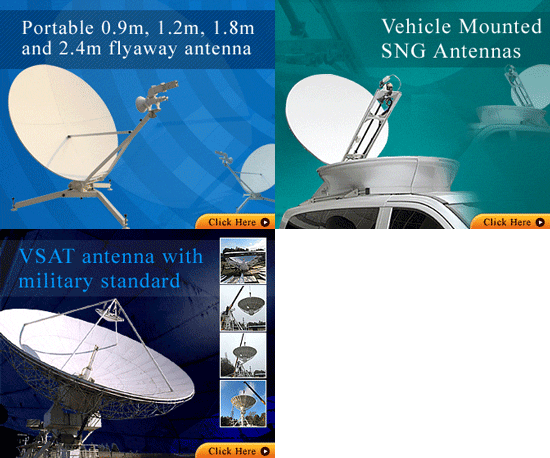
VSAT Antenna Installation
The antenna needs to be mounted where it can 'see' the satellite and where it is safe from unauthorised access. The outdoor RF unit (ORU) is mounted on the arm in front of the antenna reflector.
The outdoor RF unit comprises two radio modules: a low noise block down converter (LNB) and a transmit block up converter (BUC) plus a ortho-mode transducer (OMT) which is the joint where the transmit and receive waveguides join. A band pass and band stop microwave filter is used prior to the LNB to protect it from the transmitter signals. For circular polarisation a polariser is located between the OMT and the feed horn. The feed s are a
Ground mount:
This involves a tube lowered into a hole which is then filled in with concrete. Alternatively the tube may have a metal base plate attached so that it may be screwed to a plain concrete base using expanding bolts or similar. The pole should be accurately vertical so that when you swing the dish around to find the satellite the elevation angle stays the same all the time.
Securing the area with fencing or similar may be necessary.
Non penetrating mount:
Based on an angle iron frame covered in concrete slabs. The antenna support tube is held vertical by several angle braces. Make sure that all angle braces are tight so that the pole does not wobble or twist in the wind. Read the assembly instructions carefully. The lower and upper angle braces may need to be attached to opposite sides of the vertical pole to prevent twisting.
A permanent safety rope is advised to be attached between the dish assembly and some fixed part of the building so that the dish does not blow off the building in exceptionally high winds.
Check the building roof is strong enough to support the weight of all the concrete blocks. In many cases a non-penetrating mount is not possible due to weak roof.
IFL Cables
One or two coax cables will be required for the radio signals. These also carry low voltage DC supplies to power the LNB and BUC. The centre pin of the F connector must stick out about 2 mm. The outer braid of both coax cables must be well connected at all four ends. If the outer braid of one coax cable is disconnected somewhere there will be very strange effects.
The antenna structure should be earthed to provide some protection from lightning strikes. If the building uses PME type earthing then consult a competent electrician regarding the lightning earth connection as there is a risk of hazard if an electricity network fault arises. In some countries useful regulations exist and provide guidance on how to earth the antenna safely.
Take care connecting up both the coax and earth cables as there may be differential earth voltages at each end. A thick earth cable between the antenna structure and the indoor chassis unit should make it safe to connect up the coax cables. If in doubt use the outer of one coax to make contact between the indoor unit chassis and the antenna before plugging in the other coax, noting that the centre pin of the coax may connect up first before the outer..
The indoor data processing unit (DPU) or satellite modem
The indoor data processing unit (DPU) should be located in a dry, cool and clean place.
Safety
Installing a dish is normally dangerous. Take care not to fall down and not to drop tools on others below. Be careful with ladders - always tie off the top to some secure point. A small electric shock may make you fall off a ladder so be extra careful.
If you are a beginner, practice the complete installation at ground level before moving everything to the roof.
Accuracy of dish pointing and polarisation alignment
The dish pointing (azimuth and elevation) needs to be near perfect (within the -0.25 dB of the beam peak on transmit) as the transmit beam is narrower then the receive beam.
The feed rotation polarisation adjustment needs to be to 1 deg accuracy to ensure that you are in the very sharp null. Make this adjustment very slowly while the hub staff watch the CW signals on their spectrum analyser. Give the hub staff plenty time to make each measurement (20 seconds) and then rotate the feed a fraction while talking to them. They are looking for a signal about 25 - 35 dB down so it is not easy.

